

Ooitech offers a complete range of solar panel testing equipment for IEC61215 and IEC61730 certification, including visual inspection stations, wet leakage testers, steady state simulators, UV aging chambers, damp heat test chambers, mechanical load teste
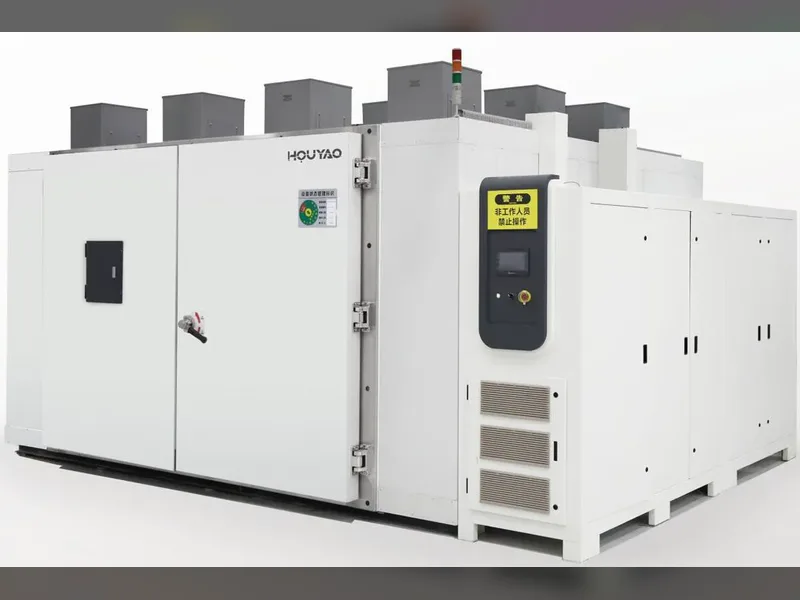
Solar Panel Testing Equipment for IEC Certification | Complete PV Module Test Solutions by Ooitech
Ooitech offers a complete range of solar panel testing equipment for IEC61215 and IEC61730 certification, including visual inspection stations, wet leakage testers, steady state simulators, UV aging chambers, damp heat test chambers, mechanical load teste
Visual Inspection
Meet the standard: IEC61215-2MQT01 IEC61730-2MST01
Test purpose: Detect and record any appearance defects and changes in PV modules.
Main Technical Parameters
| Maximum test sample size | 2600mm × 1400mm (customizable) |
|---|---|
| Support material | European standard aluminum profile frame |
| Test platform | 5mm all steel wood + blue insulating pad |
| Illumination of test platform | ≥ 1000 lux |
| Other accessories | Drawer, illuminometer, magnifying glass with scale, steel ruler |
| Optional accessories | Camera |
Wet Leakage Test System
Meeting standard: IEC61215-2MQT15 IEC61730 MST17
Test purpose: To evaluate the insulation performance of the module under wet working conditions, and verify that the moisture of rain, fog, dew or snow cannot enter the working part of the internal circuit of the module. If the moisture enters, it may cause corrosion, electric leakage or safety accidents.
Product Features
- The liquid temperature can be automatically controlled; the temperature control system adopts a constant temperature all-in-one machine to accurately control the water temperature.
- It can monitor the conductivity and temperature of liquid.
- Equipped with insulation tester, which can test the insulation and leakage of components.
- With overload, overcurrent and overvoltage alarm.
Temperature Control Tank
- The insulation tank is made of PPR material, which has good visibility and can observe the condition in the test process.
- Aluminum alloy profile support, universal brake casters installed at the bottom, drain valve for easy cleaning.
- PID automatic temperature control adjustment to meet the standard requirements of 22±2℃ (the equipment has heating and cooling functions).
- Conductivity range: 1.0~2000 μS/cm (equivalent to 500Ω·cm ~ 1,000,000Ω·cm).
Insulation Test System
Meet: IEC61215-2MQT03 IEC61730-2MST16 IEC61730-2MST17
Test purpose: Determine whether the insulation between live parts and accessible parts in the assembly is good.
| Withstand voltage output | 0.1–10KV (Up to 15kV) |
|---|---|
| Voltage accuracy | ±(2% of setting + 5V) |
| Insulation voltage output | 500–2000V (Upgradeable to 2500V) |
| Voltage accuracy (insulation) | ±(1.5% of setting + 10V) |
| Resistance range | 100KΩ – 99GΩ |
| Resistance accuracy | ±(3% of setting + 10 counts) at >500±(7% of setting + 10 counts) at<500 |
Steady State Simulator
Meeting standard: IEC61215-2MQT09 IEC61730-2MST21 IEC61730-2MST22
Test purpose: To determine the ability of components to withstand the heating effect of hot spots, such as this effect may lead to welding melting or package degradation. Defective, mismatched, partially shaded or soiled batteries can cause this defect.
Product Features
- Automatic load calculation, reasonable adjustment of system output and automatic compensation of light intensity.
- The number of light sources is small and the light is powerful. Each lamp is equipped with independent EPS to realize 50%–100% adjustable light intensity.
- Unique reflector technology and computer simulation array arrangement ensure good irradiation uniformity.
- The unique air duct design and efficient refrigeration unit can accurately control the temperature and wind speed, and the temperature control elements can be freely selected by program. The sample surface temperature control option ensures the test requirements of the sample temperature arrival time.
Main Parameters
| Light source type | Metal halogen lamp |
|---|---|
| Spectral distribution | 280nm to 3000nm |
| Irradiation intensity | 1000W/㎡ to 1300W/㎡ |
| Irradiation intensity adjustment range | 50% to 100% linear adjustable |
| Studio size | Customizable |
| Unevenness | Class B (≤5%) |
| Spectral grade | Class B (300nm to 1200nm) |
| Instability | Class A |
| Temperature range | 50℃±10℃ (expandable: -45℃ to 150℃) |
| Humidity range | 20% to 95% (humidity control can be added for high-temp/high-humidity or damp-heat simulation) |
| Temperature deviation | ≤2℃ |
| Lamp source power | 2KW / 4KW |
| Refrigeration system | Single stage refrigeration |
| Compressor brand | Bizel, Germany / Taikang, France |
| Cooling method | Air / water cooling |
| Meet the standard | IEC + UL — Accept non-standard customization |
Ultraviolet Aging Test Chamber (UV)
Meet the standard: IEC61215-2MQT10 IEC61730-2MST54
Test purpose: Conduct UV irradiation pretreatment before thermal cycling / wet freezing test of components to determine the UV attenuation of relevant materials and adhesive connections.
Product Features
- Unique reflector technology and computer simulation array arrangement ensure good irradiation uniformity.
- The unique air duct design and efficient refrigeration unit can accurately control the temperature and wind speed, and temperature control elements can be freely selected by program. The sample surface temperature control option ensures the test requirements of the sample temperature arrival time.
- The number of light sources is small and the light is powerful. Each lamp is equipped with independent EPS and can be controlled independently.
- Automatic load calculation, reasonable adjustment of system output and automatic compensation of light intensity.
Main Parameters
| Light source type | Metal halogen lamp |
|---|---|
| Spectral distribution | 280nm to 400nm |
| Irradiation intensity | ≥200W/㎡ |
| Irradiation intensity adjustment range | 50% to 100% linear adjustable |
| Studio size | Customizable |
| Unevenness | ≤15% |
| Spectral scale | UVB accounts for 3%–10% of the total UVA + UVB |
| Temperature range | 60℃±5℃ (expandable: -45℃ to 150℃) |
| Humidity range | 20% to 95% (humidity control can be added for high-temp/high-humidity or damp-heat UV) |
| Temperature deviation | ≤2℃ |
| Lamp source power | 2KW |
| Refrigeration system | Single stage refrigeration |
| Compressor brand | Bizel, Germany / Taikang, France |
| Cooling method | Air / water cooling |
| Meet the standard | IEC + UL — Accept non-standard customization |
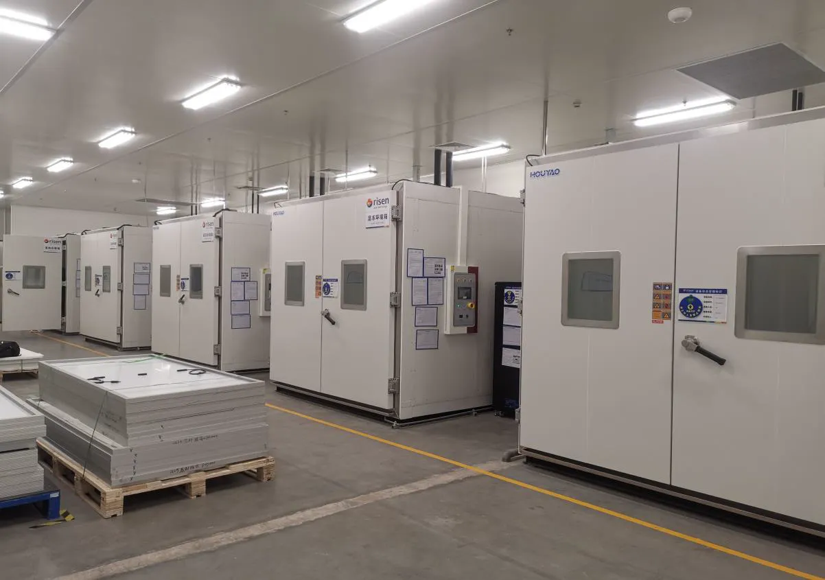
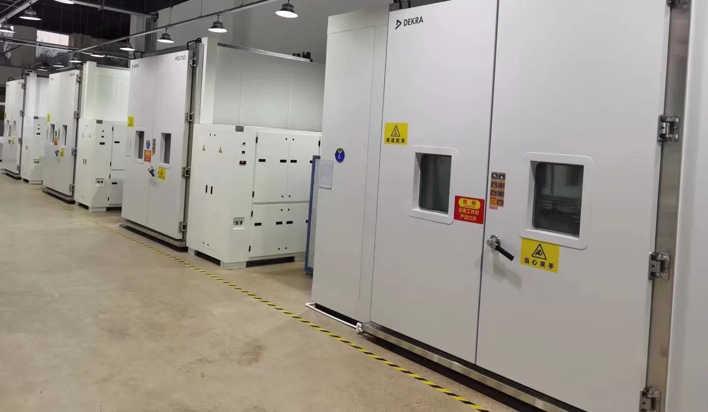
High and Low Temperature Damp Heat Test Chamber
Meeting standard: IEC61215-2 MQT11 IEC61215-2 MQT21 IEC61730-2 MST52 IEC61215-2 MQT12 IEC61730-2 MST51 IEC61730-2 MST53 IEC61215-2 MQT13 IEC61730-2 MST55 IEC61730-2 MST56
Test purpose: Determine the ability of components to withstand thermal mismatch, fatigue and other stresses caused by repeated temperature changes; determine the ability of the component to withstand the influence of high temperature, high humidity and subsequent sub-zero temperature; determine the ability of the component to withstand long-term moisture penetration.
Product Features
- Exclusive patented layered blowing technology: short temperature rise/fall time and better uniformity for tested samples.
- Automatic load calculation, reasonable regulation of system output. The latest cooling capacity control technology (thermal expansion valve + capillary + cold output) changes the traditional heater-offset method of controlling box temperature, achieving 40% energy saving compared with the traditional way.
Main Parameters
| Temperature range | -45℃ to 125℃ |
|---|---|
| Humidity range | 20%–98% RH (between 20℃ and 90℃) |
| Insulation layer thickness | ≥150mm |
| Working room size (D×W×H) mm | Customizable |
| Temperature fluctuation | ≤±0.5℃ |
| Temperature uniformity | ≤2℃ |
| Temperature rise and fall rate | Customizable |
| Humidity fluctuation | ≤±1% |
| Humidity uniformity | ≤3%RH |
| Refrigeration mode | Compressor refrigeration |
| Refrigeration system | Binary superposition |
| Compressor brand | Bizel, Germany |
| Cooling method | Water-cooling |
| Meet the standard | IEC + UL — Accept non-standard customization |
Current Continuity Monitoring System
Meet the standard: IEC61215-2 MQT11 IEC61730-2 MST52 IEC61215-2 MQT12 IEC61730-2 MST51
Test purpose: Simulate the effect of long-term thermal expansion and cold contraction of photovoltaic modules on welding performance.
Product features: Customer-defined relationship between current and temperature; built-in communication port with the environment chamber; temperature channels and current channels can be combined freely.
Main Parameters
| Input voltage | Three-phase 380VAC ±15% |
|---|---|
| Input frequency | 47–63Hz |
| Output voltage | 0–100V (customizable), resolution: 0.01V |
| Output current | 0–30A (customizable), resolution: 0.001A |
| Output power | 3000W (customizable) |
| Output current accuracy | ≤0.5% |
| Output voltage accuracy | ≤0.3% |
| Output efficiency | >90% (standard AC input, full load) |
High Temperature and Humidity Test Chamber (DH)
Meeting standard: IEC61215-2 MQT13 IEC61215-2 MQT21 IEC61730-2 MQT21 IEC62804
Test purpose: To determine the ability of the component to withstand long-term moisture penetration.
Product Features
- Automatic load calculation, reasonable regulation of system output. The latest cooling capacity control technology (thermal expansion valve + capillary + cold output), achieving 40% energy saving compared with the traditional method.
- Full-welding cabin design to prevent moisture leakage, with higher load capacity.
- Integrated sample fixture accommodates samples of different sizes, with full insulation.
Main Parameters
| Temperature range | RT–125℃ |
|---|---|
| Humidity range | 20%–98% RH (between 20℃ and 90℃) |
| Insulation layer thickness | ≥150mm |
| Working room size (D×W×H) mm | Customizable |
| Temperature fluctuation | ≤±0.5℃ |
| Temperature uniformity | ≤2℃ |
| Temperature rise and fall rate | Customizable |
| Humidity fluctuation | ≤±1% |
| Humidity uniformity | ≤3%RH |
| Cooling method | Air / water cooling |
| Meet the standard | IEC + UL — Accept non-standard customization |
PID Test System
Meeting standard: IEC61215-2 MQT21 IEC62804
Product Features
- PID power supply has multi-channel output, which can provide multiple components for simultaneous testing; voltage is continuously adjustable and displayed in real time.
- The power supplies are independent of each other and can output different polarity and different voltage values at the same time.
- PID monitors communication and outputs high voltage to test samples according to customer-defined time requirements. The system monitors internal temperature and humidity of the environmental test chamber in accordance with the latest standards (online communication with high-temperature and high-humidity equipment). When the environmental test chamber fails, the PID power supply automatically receives the fault information and forces output to "0", preventing damage to test samples and ensuring equipment safety.
Main Parameters
| Input voltage | AC 220V ±10% |
|---|---|
| Output voltage | DC -2000V to +2000V (continuously adjustable); upgradeable to DC -2500V to +2500V |
| Voltage accuracy | Voltage fluctuation within 500 hours of continuous output at 1000V / 1500V / 2000V: ≤0.5% |
| Maximum rated current | 250 μA / passageway |
| Current accuracy | 1μA + 1% F·S |
| Test channel | Customer customization |
Static Mechanical Load Test (Sand Pressure)
Meet the standard: IEC61215-2MQT16 IEC61730-2 MST34
Test purpose: Determine the ability of components to withstand static loads such as wind, snow or icing.
Main Equipment Parameters
| Maximum size of test sample | 2600 × 1400mm (customizable) |
|---|---|
| Maximum load of test equipment | ≤12500 Pa |
| Pressure control accuracy | ±5% (self-prepared according to the number of sandbags) |
| Circuit continuity system | DC power supply: 60V / 5A (customizable); real-time monitoring of internal continuity of components |
| Sandbag specification | 10.0 ± 0.25 kg/bag |
| Number of shape variables | 1–5 (optional) |
| Shape variable accuracy | ±0.5mm |
| Shape variable range | ±200mm |
Product Features
- Customized test platform fixture adjustable according to sample installation mode: long frame, short frame, and mounting hole installation modes are all supported.
- Shape variable test system supports up to 5 monitoring points simultaneously; monitoring point positions are arbitrarily adjustable.
- Visual icon control and Excel output; current output control to meet diverse customer requirements.
Cyclic (Dynamic) Mechanical Load Testing (DML)
Meet the standard: IEC61215-2MQT16 IEC61215-2MQT20 IEC61730-2 MST34 IEC TS62782:2016
Test purpose: Determine the ability of components to withstand static and dynamic loads under conditions such as wind, snow or icing.
Design Description
The system simulates dynamic load using pneumatic cylinders with suction cups. Pressure mode: suction cup + pressure sensor + cylinder + proportional valve + PLC. Each cylinder drives one suction cup; a pull-pressure sensor is installed on each cylinder piston rod. Air pressure is calculated by PLC based on real-time feedback from the pressure sensors, and cylinder movement is controlled by adjusting the proportional valve opening to achieve precise force control. Each cylinder is an independent control module. Periodic load pressure tests are conducted on the installation plane of the component. The main frame is 8080 European standard aluminum profile, designed to accommodate conventional pressure block installation, screw hole installation, and double-glass component installation. The equipment also provides real-time monitoring of component shape variables, current continuity, and component temperature during testing.
Main Technical Parameters
| PV module size | ≤2600 × 1400mm (customizable) |
|---|---|
| Height range of PV module + mounting beam | 50mm–350mm (compatible with sun-tracking installation) |
| Test capacity | One module at a time |
| Pressurization mode | Cylinder |
| Number of cylinders | 6×12 = 72 (optional) |
| Number of pressure sensors | 6×12 = 72 (optional) |
| Pressure sensor accuracy | ≤0.02% F·S |
| Pressure mode | Pulling and pressing (two directions) |
| Bore stroke | 300mm (-150mm ~ +150mm) |
| Suction cup center distance and edge distance | ≤20cm (non-standard: separate specification) |
| Cylinder position (spacing movable) | Center distance arbitrarily adjustable within 2600×1400mm range (150mm ~ 250mm) |
| Test frequency | 3~7 cycles/min |
| Down pressure maximum pressure | 12,000 Pa |
| Maximum pull-up pressure | -7,200 Pa |
| Pressure control accuracy (static load) | 1% |
| Suction cup diameter | 100mm |
| Suction cup variable angle | 15° |
| Static load non-uniformity (5 min) | Test pressure ≥2400 Pa: non-uniformity ≤3%Test pressure ≥3600 Pa: non-uniformity ≤2% |
| Dynamic load non-uniformity (5 min) | Test pressure ≥1000 Pa: non-uniformity ≤5% |
| Shape variable sensor | 1~5 positions (movable) |
| Shape variable sensor accuracy | ±0.5mm |
| Cylinder brand | Imported from Japan (original) |
| Proportional valve brand | Imported from Japan (original) |
| Suction cup brand | Imported from Japan (original) |
| Controller brand | Siemens PLC (Germany) |
| Control mode | PLC + HMI (Shanghai Houyao proprietary program) |
| Other | Low-temperature load option available: -40℃ (optional) |
| Power specification | 60V 5A (customizable) |
| Component installation method | Pressure block installation, screw hole installation, sun-tracking bracket installation |
Product Features
- Control software synchronously collects pressure, component pressure, component temperature, continuity current, component voltage, and shape variable data for each cylinder.
- Humanized HMI graphics; arbitrary current setting to meet diverse customer needs.
- Visual icon display and Excel output format.
- Optional special load cell for periodic equipment verification.
Hail Test
Meet the standard: IEC61215-2MQT17
Test purpose: Evaluate the ability of the component to withstand hail impact.
Main Technical Parameters
| Ice ball specifications | 25mm; 35mm; 45mm; 55mm; 65mm; 75mm (optional) |
|---|---|
| Ice ball diameter accuracy | ≤±5% |
| Ice ball mass accuracy | ≤±2% |
| Ice ball generation speed control accuracy | ≤±5% |
| Speed sensor accuracy | ≤±2% |
| Electronic balance | 100g/0.1mg; 250g/0.1mg |
| Refrigerator | 2 sets |
Product Features
The ice ball firing speed is measurable. The speed measuring unit uses two photoelectric sensors mounted in front of the transmitting tube, with a 10cm gap between them. Speed is calculated by V = S/T and displayed in real time. The speed test device consists of three parts: detection sensor, high-speed response module, and software module. Photoelectric sensors and a programmable controller with stable performance are used for speed measurement.
Bypass Diode Testing
Meet the standard: IEC61215-2MQT18 IEC61730-2 MST25
Test purpose: To evaluate the thermal performance of bypass diodes and their long-term reliability against harmful effects such as hot spots.
Product Features
- The system automatically forms a fitting curve to judge test results.
- The equipment is equipped with an oscilloscope to capture the pulse curve.
Main Equipment Parameters
| Pulse power supply — current | 30A (customizable), deviation ±2% |
|---|---|
| Pulse power supply — pulse width | 800 μs – 1100 μs adjustable |
| Forward constant current source — current | 50A (customizable) |
| Forward constant current source — accuracy | 0.05% + 0.5% F·S |
| Voltage acquisition channels | 8 channels |
| Temperature acquisition channels | 8 channels |
Cut Susceptibility Test
Meet the standard: IEC61730-2MQT12
Test purpose: Determine whether polymer materials, as components of front and rear surfaces, can withstand routine operations during installation and maintenance without the risk of personal electric shock.
Main Technical Parameters
| A — Distance from rotating shaft to center point of bearing | 150mm |
|---|---|
| B — Distance from rotating shaft to test point | 170mm |
| C — Carbon steel band thickness | 0.64mm ± 0.05mm (saw blade recommended) |
| D — Angle between carbon steel strip and horizontal plane | 140° |
| Q — Force applied at point Q | 8.9N ± 0.5N |
| R — Radius of arc at tip | 0.115mm ± 0.025mm |
| T — Angle of T | 90° ± 2° |
| Speed requirement | 150mm/s ± 30mm/s |
Robustness of Terminations
Meet the standard: IEC61215-2MQT14 IEC61730-2 MST42
Test purpose: To determine whether the leading-out end and its attachment to the component can withstand the force during normal installation and operation.
Main Parameters
| Torsion test — test duration | 1 min (settable) |
|---|---|
| Torsion test — deflection angle | Display / physical display |
| Adhesive force test — load | 40N |
| Adhesive force test — test time | 10 ± 1s |
| Adhesive force test — control mode | PLC control |
| Adhesive force test — fixture | Junction box custom fixture |
| Tensile test — weight configuration | 4N, 30N, 40N |
| Tensile test — test frequency | Adjustable |
Continuity Test of Equipotential Bonding
Meet the standard: IEC61730-2MQT13
Test purpose: Prove that all exposed conductor surfaces of the assembly are connected and grounded to each other.
The BSQ9930A photovoltaic grounding resistance tester is specially designed for the grounding resistance characteristics of photovoltaic modules (also known as grounding continuity tester). Programmable output test current DC 10~100A, test range up to 0.01μΩ~600mΩ, stable test and high precision. It has test line conductivity detection function, three groups of test modes, and can realize programmable test and sorting. RS485 interface is optional; instrument networking can be easily realized through Modbus communication protocol. Complies with photovoltaic standard IEC61730.
Product Features
- DC output 10A–100A, capable of meeting three times the maximum current of a photovoltaic panel.
- Resistance test range: 0.01μΩ ~ 600mΩ, stable reading.
- Test line anomaly detection function to prevent test misjudgment.
- Various interface configurations suitable for supporting automatic test systems.
Main Equipment Parameters
| Test parameter | Resistance |
|---|---|
| Output current and accuracy | Program controlled DC 10A–100A |
| Test range | 0.01μΩ – 600mΩ |
| Display accuracy | 0.001A |
| Maximum output power | 600W |
| Test time | 0.1S – 999.9S |
| Comparator | Three groups of test conditions saved; audible and visual pass/fail indication |
| Display results | Current, resistance, time, and sorting information |
| Standard interface | RS232C; RS485 (optional); PLC interface (optional) |
| Communication protocol | Modbus |
| Other | Abnormal alarm prompt for test line |
| Power requirements | Voltage: 198VAC~240VAC; Frequency: 47Hz–63Hz; Power: 650VA |
| Size and weight | 344(L) × 280(W) × 99(H) mm; Weight: 5.2 kg |
| Accessories | Four-terminal test clamp |
Impulse Voltage Test
Meet the standard: IEC61730-2MST14
Test purpose: This test is used to verify the ability of solid insulating materials in components to withstand overvoltage caused by atmospheric environment. It also relates to the overvoltage state caused by the switching of low-voltage equipment.
The BSQ_PV30 is specially designed for testing the pulse voltage of solar cell modules (solar panels). The generator can generate surge voltage waveform 1.2/50μs meeting IEC60060-1/2 standard. The voltage can reach 30KV and meets the standard requirements of IEC61730-1/2 and EN61730-1.
Technical Parameters
| Pulse output voltage (adjustable ±3%) | 2.0~30KV |
|---|---|
| Voltage accuracy | ≤3% |
| Voltage resolution | 10V |
| Rise time | 1.2 ± 30% μs |
| Falling time | 50μs ± 20% |
| Polarity | Positive / Negative |
| Maximum energy storage | 100J |
| Charging time at maximum charging voltage | Approximately 10 sec |
| Internal load capacitance | 4100pF ± 10% |
Supporting Accessories
- Oscilloscope: 1 set
- Attenuation rod (attenuation multiple 1000:1): 1 set
- Insulation protection grade insulation pad: 2 pieces
- Insulating gloves: 1 pair
Reverse Current Overload Test
Meet the standard: IEC61730-2MST26
Test purpose: Evaluate the conductive material of the external insulation layer of the module. In case of reverse current fault and before the overcurrent protector disconnects the circuit, the battery and interconnection strip of the module will be forced to heat up to consume energy. This test is used to determine the resistance of components to ignition and fire under this state.
Functional Features
- Up to 100A current can be supplied to components.
- The reverse current can be set and monitored in real time (optional).
- Historical data query function (optional).
- All data exported in Excel format (optional).
- Temperature measurement range: -20℃ ~ 200℃, accuracy: 0.5℃ (optional).
- Pine board can provide third-party thermal conductivity report.
Power Specification (BSQ6512D)
| Input voltage | Three-phase 380VAC ±15% |
|---|---|
| Input frequency | 47–63Hz |
| Output voltage | 0~100V (customizable) |
| Output current | 0–100A (customizable) |
| Output power | 10kW (customizable) |
| Current accuracy (constant current CC) | ≤0.05% + 0.5% F·S (set value) |
| Voltage accuracy (constant voltage CV) | ≤0.05% + 0.3% F·S (set value) |
| Efficiency | ≥90% (standard AC input, full load) |
| Display mode | Four-digit LED nixie tube display |
| Display resolution | 4-bit display accuracy |
| Instrument accuracy | ±0.1% |
| Remote analog monitoring | Analog control, USB / LAN |
| Remote programming/monitoring accuracy — voltage | 2mV |
| Remote programming/monitoring accuracy — current | 2mA |
| Protection | Input undervoltage, output overvoltage, overheating, short circuit protection |
| Cooling mode | Fan(s) |
| Other accessories | Pine board, rice paper |
Module Breakage Test
Meet the standard: IEC61730-2MST32
Test purpose: Determine the risk factor of scratch or stab after component rupture, and the toughening strength of toughened glass.
Impact Bag Specification
The impact bag is a leather bag similar in shape and size to a hanging bag, filled with lead pellets (diameter 2.5~3.0mm, i.e. #7.5 shot) to the required weight. The outer surface of the bag is wrapped with tape; during testing, the impact bag is completely wrapped with 1.3cm-wide glass fiber-reinforced pressure-sensitive tape.
Salt Mist Test
Meet the standard: IEC60068-2-52 IEC61701-2011
Test purpose: To determine the corrosion resistance of components and their packaging materials.
The equipment uses saline solution or acidic saline solution and does not move the test sample in a test box to achieve four cycle (alternating) test effects: salt spray, drying, constant temperature and humidity at standard atmospheric pressure, and low-temperature storage. It accelerates corrosion of materials or products according to test requirements, and tests the damage degree within a certain time range.
Main Technical Parameters
| Temperature range | 10–100℃ |
|---|---|
| Temperature deviation | ≤±1.0℃ |
| Temperature repeatability | ≤±0.5℃ |
| Temperature uniformity | ≤2℃ |
| Humidity range | 25%–98% RH |
| Humidity deviation | +2~-3% (>75%RH); ±5% (≤75%RH) |
| Humidity fluctuation | ≤1.5% RH |
| Humidity uniformity | ≤3% RH |
| Salt fog sedimentation | Continuously collect salt spray at any point in the exposed area for at least 8 hours using 80cm utensils; deposition rate: 1~2mL/h (number of test utensils: 3×3) |
| Spray mode | Pneumatic; continuous and intermittent spray freely adjustable |
| Air source pressure | 0.17~0.4 mPa |
| Volume of brine tank | ≥500L |
| Internal bearing capacity | ≥1000 kg/m² |
| Test mode | Constant value and program test (salt spray and damp heat can be switched automatically) |
| Sample placement | Bracket places component at 30° angle to the Y-axis direction |
| Salt spray method | Baffle type — salt spray is not directly sprayed on the sample |
| Salt fog indoor roof | Top included angle approximately 120° to prevent droplets from dripping directly on the sample |
| Indoor bin pressure | Two 110×110mm automatic control balance windows installed at appropriate positions |
| Salt spray test level | Level 1–7 salt spray test |
Request a Custom Quote
Tell us about your project — production capacity (MW/year), cell technology, factory location and timeline. Our engineers will reply with a tailored proposal within 24 hours.